Intended use
The Starter Kit G is intended solely for operation with the Plasma high-voltage source and a plasma generator from RP.
Coupled with a suitable plasma generator, the machine is intended solely for the plasma treatment of surfaces (metals, textiles, glass, plastics) to activate, clean, coat or remove residue at atmospheric pressure.
Under no circumstances may the system be used by non-trained persons.
System description

Function
Combined with a Plasma supply and a plasma generator, the Starter Kit G is used for the atmospheric plasma treatment/pre-treatment of various material surfaces. The software provided allows the process data used to be monitored and saved with ease. It also simplifies diagnosis of errors.
It is intended for industrial applications where surfaces are activated or cleaned with plasma prior to printing, gluing or painting. It may also be used for surface-coating.
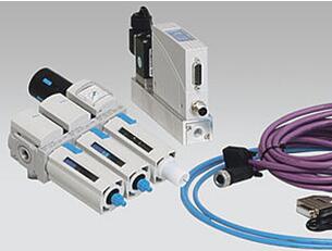
Description for Starter Kit G
No. Component
1 Maintenance unit for pneumatic preparation
2 CAN bus cable for MFC*
3 External power plug for MFC*
4 Pneumatic hose, 6 mm dia.
5 MFC
* Mass flow controller
Scope of delivery for Starter Kit G
The scope of delivery includes the following components:
• Maintenance unit
• CAN bus cable for MFC
• External power plug
• Pneumatic hose
• MFC
• Operating instructions
Installation requirements :
Before installing the machine, the following must be true:
• There must be an appropriate gas supply.
• The components must be undamaged.
• If installing as a permanent installation or in a building, a suitable switch or circuit breaker that satisfies national safety requirements (in Germany: VDE 0100) must be fitted as an upstream all-pole cut-off device that will disconnect the system from the power supply. This cut-off device should be fitted near the machine and must be easily accessible to the user. The switch must also be labelled as the cut-off device for the machine.
• A Windows XP, Vista or Windows 7/8 operating system is needed
• Screen resolution of at least 1024x768
Installing and commissioning Starter Kit E and Starter Kit G
To install and commission Starter Kits E and G, proceed as follows:
1. Perform steps 1-4 for starting up Starter Kit E
2. Connect Plasma supply with the MFC using the CAN bus cable MFC (#5). No further terminal resistor is needed
3. Now connect the power pack provided to the MFC and set a node number of 11 at the point on the MFC indicated by an arrow (#6)
4. For the gas section, connect the maintenance unit to the MFC using the pneumatic hose (#7 and #8)
5. Now establish a connection between the Plasma generator and the MFC using the pneumatic hose (#9)
6. A suitable gas supply (nitrogen or compressed air) can now be connected to the maintenance unit (#10) Position of MFC and maintenance unit
The maintenance unit and MFC should always be operated in a vertical position, otherwise faults and inaccuracies may result


Starter Kit E and G are installed.